November 23, 2022

DIY Drone Update #2 - Actually Building It!

This project has been a long time in the making. My first post about this drone was all the way back in November 2019, where I sourced all the parts but didn't actually build it. But at the end of 2021 (I know, also a long time ago), I actually built and successfully flew it!

Stepping back to 2021, I still had not replaced the broken motor, so I ordered one of eBay, which this time came with all the accessories. I guess you get what you pay for. I also ordered a proper 12V power supply for the battery charger, not because the DIY version was dangerous or failed, but because it used more space than necessary, and was probably not that efficient. Maybe I'll build one of those custom desktop power supplies out of it one day.

The First-Person View (FPV) module connected to the Flight Controller


 (FC)
 
I started by connecting up the FPV module to the Flight Controller, since it was the easiest component to start with and allowed me to see if the camera and On-Screen Display (OSD) on the Flight Controller worked correctly. Thankfully, when I powered the board via the USB port, I was successfully able to connect to the video feed from my headset (which after purchasing, I have now realised is illegal to use in Australia without authorisation that I don't have). 

At this point I met up with some friends who had slightly more experience with RC aircraft than me, and we got going on connecting the transceiver to ensure that reliable control could be made when the motors are connected. To do this, the PPM pads were shorted to specify which protocol was to be used. After configuring the FC within Betaflight Configurator, the switches, dials and sticks all could be seen to be working. Mainly, I was able to configure the throttle to be the correct stick and in the correct direction, and that a safety switch would be able to instantly disable the motors when activated. 

Now that all the simple (and in the case of the transceiver, essential) components were connected, I began to connect all the motors. Firstly, the motors were connected to each of the 4 Electronic Speed Controllers (ESCs), which control the amount of current going to the motors, and allow for the drone to know what speed the motors are rotating at. These ESCs also have extra connectivity, allowing for their BLHeli firmware to be updated, but also configured beyond that of pure Betaflight. 

The (amazing) workspace much of the drone was built in

The flight controller I used only had one pad for soldering all the live and ground wires from the motors to, so I purchased a distribution board which had pads for each of the 4 ESC's power cables, as well as the battery and the power for the Flight Controller. The rest of the wires were soldered directly to the FC, which facilitate the control of each of the individual motors.

While soldering it together, I had to make sure the wires were long or short enough to get to where they want to go, but also make sure that nothing would interfere with the props on each of the motors. I prevented wires from getting snagged using electrical tape, which I also used underneath live components such as the ESC's and Flight Controller to ensure that nothing shorted on the carbon fibre frame.

Once it was all within the frame, I did a quick test of each motor through Betaflight (with the props removed), to check that all the motors worked, were in the correct layout, and that they were all spinning the correct direction. I quickly discovered one of the motors spinning the wrong direction, which was easily fixed by unsoldering and swapping the wires around. 

Eventually, once everything seemed like it was working correctly, including the safety switch on the controller, I attached the props and took it outside to test if it would fly. And it did! Although I am not very good at flying it, especially landing... It's still in one piece, but I have a lot of practice to do in the simulator before flying it properly. 

The completed drone (minus battery)
So now it is complete and works, I hope to fly it soon once I've spent some more time in the simulator. I also have an RC plane now, which I also cannot fly well, so there may be more aerospace related content in the future if either of those get off the ground (pun intended). 

July 31, 2022

DIY UV Curing Station

When I first got into resin printing, I found the whole process extremely messy and tedious. There were also so many chances for something to go catastrophically wrong. In light of this, I didn't want to invest significant amounts of money into it, as my goal was only to get an idea for what it is, and if it has a viable future as a hobby. This meant I had to DIY many steps of the process, mainly around the post-processing. 

Through some quick internet searching, I came across many pages which recommended that the sun is a viable alternative to a curing station, since it produces UV light. And since curing stations can cost upwards of AU$100, this was an easy solution. The only downsides were that curing can only happen when it is sunny, and it takes longer as the concentration of UV is lower outside compared to dedicated LEDs. 

Looking into how a UV curing station worked, I realised it would be really easy to build my own for much less. And especially since every COVID-19 kit I had bought came with an UV torch, which just happened to be within the correct wavelength, I had a whole bunch of UV LEDs ready to go. 

The COVID-19 self-test kits I had ordered were from Hough, and by reading the instructions I could see that the torch wavelength should be 365nm, as this is the wavelength the test reacts to. By comparing this to the range that my resin reacts to, I discovered that it lay within the range, being 355-410nm. 

Since these torches are essentially free, and in huge supply, I chose to build a curing station based around them. To start, I had a look at what curing stations for sale look like, and how their LEDs are arranged. I found that most have a vertical strip, with some also having an overhang on a hinge to better illuminate the tops of objects. Based off this research, and my limited modelling skills (which I hope to work on), I decided to start with just the vertical stick design. 

Firstly, I started brainstorming different ways to make the torches stay in place in the most simple way possible. I ended up using a combination of a small shelf, as well as a hole through the model with a little lip to prevent it falling out the end to hold the torches in place.

The small shelf with the lip to prevent the torch falling out. 


While making the shelves, I first tried to model them manually, which ended with a very poor, hard to replicate or re-dimension design. Because of this, I stumbled across the 'arc slot' shape under the draw menu, which allowed for the perfect shape for the shelf, all with easy to assign dimensions that aligned perfectly with the hole. 

The hardest part to get right, which still has issues, was the base. Since the torches are quite heavy, and the batteries are quite far away from where they are attached to the model, it makes the design's centre of mass very far over, meaning it falls over quite regularly. 

The first design I tried was a solid rectangular base, which was simple to model and would serve a solid starting point. 

The first iteration of the stand.

I quickly realised that the base was not large enough, and when loaded up with torches could not stand up correctly.
I also discovered that I had entered the dimensions on the hole and shelf incorrectly, meaning that I had to make them larger to actually fit the torches without friction. Thank goodness I put the time in to dimension properly, and I hope this serve as a lesson for everyone who doesn't already do this. 

My next attempt at fixing the leg issue was also an attempt at saving time and filament by turning the large rectangular base into two small legs. This also allowed me to practice using the different forms of dimensions to make sure the angles matched, as well as the lengths. 

After printing this second iteration, I found that the holes were not the correct size, but it still did not stand up on it's own when all the torches were inserted. 

The second iteration of the stand.

Although it could not stand by itself, I soon realised I could use both of the stands in combination to support the two ends of the torch, which worked wonderfully. 

The two stands used together to hold all the torches.

 Now that the stand was mostly complete, I began to consider how to rotate the models so the light reaches all sides. Looking at how the proper stations achieved this, I ordered a solar turntable that can both be powered by batteries as well as the UV lights themselves. This works great, as I don't need to keep removing the battery when it is not in use.

The solar turntable. 


This also provided a potential solution to the torch issue, where the base can be held in place by the turntable and it's weight, especially when using batteries. The only issue with this method is that all the previous designs had been designed so they could be printed face down without supports, although having parts jutting out both sides means that it needs to be printed vertically with supports for all the shelves, increasing filament waste and also print time. It also has the potential to weaken the model, as the adhesion between the layers is aligned with the force from the weight of the torches, meaning it could just snap, although I can only speculate as I have not tried printing this way as of writing. 

As you may have noticed, all these models were printed on my filament-based Ender 5, which highlights how much easier filament is to work with, since, especially for these non-aesthetic models, it does not require much, if any, post-processing. And, since I have limited time to spend printing and processing, it makes more sense for me. 

So while I plan to try this out with prints in the future, as of writing I had no projects pressing enough or the time to actually complete them with resin, although I do plan to do a follow-up in the future about my experiences with resin printing, and comparing it to filament-based printers. Hopefully in that post, I can shed some more light (pun intended) on how effective this design is. 

June 22, 2022

Flipper Zero - Hands-on and Impressions

I placed my Kickstarter pledge for the Flipper Zero all the way back in August 2020, and at the time it was estimated that they would be delivered in February 2021. But with COVID-19 lockdowns and supply chain issues, this timeline was quickly revised. 

Finally, in May 2022, I received my device. But was it worth the wait?

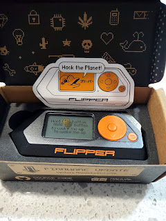
Flipper Zero in it's box, accompanied by a cute sticker!

May 31, 2022

Building a DIY Fume Extractor Fan

Ever since I started soldering, I knew that ventilation was key. Especially when working with leaded solder, the fumes can be extremely harmful, and being able to vent, or in the case of this post, capture the fumes, can greatly decrease the health risks associated. 

The goal of this project was simple. Design a simple holder for a carbon filter and standard 12V PC case fan for less than what I could buy.

I started by investigating what was already available on the market, only to find that all the options were quite expensive, at over AU$50, but not of the quality I would accept for that price. 

A fume extractor that costs AU$75

From these findings, I set out to make my own version, and while I have not fully completed this model, I have made the most key part to get a prototype working. 

The design consists of 2 parts: the main assembly, and the lid/mount combo. The main assembly consists of 2 slots that fit a 140mm PC fan, and a carbon filter. The fan I am using is from an old PC I picked up a few years ago, and features a molex power connector and a 3-speed switch as a bonus, while the carbon filter was purchased off eBay as a 4-pack for under AU$7.

Factoring in that a cheap 140mm fan can be bought off eBay for AU$12 and a few dollars in time and materials for the 3D-Printed components, this design comes in significantly cheaper than a store-bought alternative. 

The main assembly with a fan and filter installed


The final part that I am yet to design is the lid/mount, which will lock all the components inside so they cannot fall out, as well as allow the model to be attached to a stand or arm for optimal positioning through the planned use of a threaded insert, which I hope to attempt installing using the soldering-iron method, which melts it into place.
Also, the lid will allow for the installation of the barrel connector, which will replace the molex power connector so the fan can easily be plugged in to an external 12V power supply.

While this is definitely one of the simpler projects I have worked on, having it so simple has allowed me to actually (mostly) complete it, unlike many of my other projects, especially while I juggle these projects, school and work.

To make one for yourself, the model can be accessed at Thangs and at Printables

April 18, 2022

How Far Has 3D Printing Come? - Anet A8 vs Ender 5 (Easter Special)

I still remember the Christmas morning of 2017, when I opened the gift from my parents to find an Anet A8 3D Printer kit. Before this moment, I never even considered being able to afford this futuristic technology, let alone actually owning one. But my parents knew my love for technology well, and timed this gift just perfectly with the rapid growth in the 3D Printing space.

The Anet A8 after it's first power-on test.

Anet A8 First Impressions

When I first assembled it, I had no idea how to use a 3D Printer, let alone how they work. But having such a bare-bones kit allowed for me to learn through using it all the tips and tricks from fixing the numerous issues to improving print quality. If I had gotten a Prusa i3 instead, I feel I would have missed out on much of the knowledge I gained. 

What's Changed with Newer Printers?

While most 3D Printers now have magnetic or glass beds, the A8 used painters tape, which was great when I was first learning and regularly did a terrible job at levelling the bed, but quickly became obsolete due to the rough texture it left on the bottom of prints. The amazing thing about this bed was that it was heated, which was not a feature all printers possessed at the time. This allowed for much better prints as bed adhesion could be greatly improved without using large brims and glue sticks.

While this was all great, the main improvements that newer printers now feature are greatly improved safety. The Anet A8 was notorious for setting itself alight, be it from the horrible hotbed connector that would break off and short, or the power supply that I personally had to replace after it started sparking. The stories I heard about this printer have still made me paranoid to this day about having my Ender 5 print overnight or when I'm not at home, which makes long prints impossible. 

Enter the Ender 3 & 5

Towards the end of 2019 and into 2020, the Ender 5 and it's smaller sibling the Ender 3 were the new recommendations over the Anet A8, with the Ender 3 becoming the new most popular printer. The key improvements with these printers were all metal frames, which the A8's acrylic frame could not compete with, as well as increased reliability and print quality. 

While the Ender 3 is a direct competitor to the A8 with it's "T" shape, the Ender 5 is a "Box" printer with a square frame, which adds further rigidity, but also bulk. 

Comparing the Print Quality

Around Easter in 2018, 4 months after I first assembled the A8, I downloaded Easter Egg models off Thingiverse and printed one of them to celebrate the event. Now, 4 years later, I sliced the same file for the Ender 5 and printed it again to compare the quality. 

Ender 5 (Left), and Anet A8 (Right)
Sadly, the Anet A8 version was scaled at the time, and as it has been significantly upgraded and then decommissioned, I am unable to create a full size version. Although, in light of this, the main issue with the Anet A8 can still be seen, being the lacking in resolution. 

Firstly, the A8 used a 0.4mm nozzle compared the to 0.2mm on the Ender 5, but this is not the main culprit. The acrylic frame of the A8 allowed for the nozzle to flex it during fast movements, leading to the "fuzzy" effect that can be seen. As the Ender 5 has a metal frame, this is absent on it's model.

Secondly, the Anet A8 featured a direct-drive extruder, which means the extruder motor and nozzle are both on the carriage which is moving around quickly. This means that there is more weight on the carriage, leading to slower acceleration and deceleration, as well as extra inertia leading to the print-head moving further than it should before recoiling. While many printers, such as the Ender 3 S1, still use a direct-drive extruder, the Ender 5 uses a bowden extruder, which has the extruder motor attached to the frame with a tube running to the extruder on the carriage, allowing for the carriage to move quicker due to the reduced weight, although the belts still produce a small amount of recoil, but it is significantly lower than it was in the past. 

 What about more recently and in the future?

The Ender 5 is definitely not the cutting edge of printers, having been released in 2019. Printers from companies such as Artillery, Anycubic and Elegoo are taking the market by storm, and future machines such as the AnkerMake M5 may be the biggest innovation in the space in years. So while printers are already amazing, the move now is to make it easier to achieve the same results. 

In regards to quality, there are also resin printers available now with insanely high resolutions, making it possible to make highly detailed models and small parts that were previously impossible with FDM printers.

A Final Easter Treat

Since I had the printer already running, I decided to print a set of rabbits to test the overhangs, but also to celebrate the holiday. Making use of the awesome translucent green PLA I bought, I was able to print 2 rabbits with one using the normal Cura supports, and the other tree supports.

Normal Supports (Left) vs Tree Supports (Right)
First up, the normal supports was printed using the touching buildplate setting to make it more comparable to tree supports. The print took 5hrs, 49mins and 27secs. Shortly into the print, the support for the hand collapsed, meaning the bottom of the left hand did not complete, although thankfully the print saved itself and completed everything else successfully. 

Next up, the tree supports model took 6hrs, 30mins and 32secs, which is ~40mins longer than the normal supports, probably due to it using slightly more travel. The benefit of tree supports was on full show, with the model using less material but also supporting the entire overhang instead of just the part that's directly over the bed, as the "branches" bend and insert themselves between the gaps in the model, as well as wrap themselves around the model for minimum filament use. They are also hollow, meaning they are super easy to remove and, once again, use less material than the solid normal supports. 

In regards to removing the supports, both took a similar amount of time to remove, with most of the time spent removing the internal supports, as they were both quite secured to the inside of the head, which was too deep for the side-cutters. 

Conclusion

As always, if you liked this post, you can find all my other 3D Printing content here, and also through the tags below or in the sidebar. 

If you have any feedback or thoughts, please leave it in the comments below, and thanks again for reading!

March 31, 2022

Thumby - Hands-on Review of the Keychain Game Boy

Kickstarter projects have not failed to impress over the years. Every since I first backed the Circuitmess MAKERphone in 2019, I have always found it incredible how many kinds of products people have been able to produce through the platform. And while some of these do take longer than expected to arrive (looking at you, Flipper Zero), when they do, I have always been blown away. 

The Thumby is no exception. 

Created by the team at TinyCircuits, this is not their first foray into tiny electronics. In fact, I'd say the Thumby is a culmination of all their previous work, taking the TinyArcade, TinyTV, and all their tiny electronics knowledge and making it into this incredibly tiny keychain game console. 

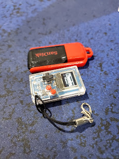
When it arrived, I was shocked at how small the box was. It was smaller than I thought the device would be, and the device inside was even smaller! With the device being just 29.5mm x 18mm x 8.5mm in size and only weighing only 4.7g, it is so insanely small, it's hard to convey it through photos.

Thumby next to a USB stick

The version I received is the special clear edition, with most units being a grey Game Boy colour scheme. The benefits of the clear case including seeing how small the components inside are (there's a battery in there!), as well as it just looking absolutely cool. I hope more companies bring back clear acrylic cases, because they still look awesome.
The PCB Commemorative Keychain that also came with the Thumby


As it is a game console, it is able to run a variety of games utilising it's tiny D-Pad and A/B buttons, which require fingernails to actually press reliably. On the Monochrome OLED, animations are smooth in menus with it's 60FPS refresh rate and games such as Saur Run (Chrome Dinosaur Game clone) are crazy clear, even during fast side-scrolling motion. The OLED is also surprisingly crisp for it's size, with the screen being 72x40 pixels. With this screen size, because of how few pixels there are, text takes up a large section of the screen if it is meant to be readable, which limits overlays and other text-based game features.
The Thumby also somehow fits a tiny buzzer inside, so old "beeps" and "boops" are possible, although because of it's size it is extremely quiet.
The final cool feature of the Thumby's gameplay is that is supports multiplayer over their custom Micro-USB to Micro-USB link cables, allowing for competitive Tennis as well as other games in the future.

For me personally, the coolest aspect of this console is not that you can play games, but you can easily make more yourself. As the Thumby is based on the RP2040 processor found in the Raspberry Pi Pico, it supports programming in multiple languages including Python and C, although the officially supported programming method is through the browser, and allows for programming in MicroPython without any additional software. Sadly, WebSerial is only available in Chrome and Edge, so Safari and Firefox users are out of luck, although the included emulator can still be used in these browsers, as well as for people who don't have a physical Thumby.

The Thumby Code Web Editor, with it's built-in emulator

If you are willing to tinker and want a more fully-featured IDE, this guide on using Visual Studio Code is also available, although I could not get it to work on my Linux installation. For a more basic offline IDE, Thonny is also available, and is the easiest way to code without a browser.

So who is the Thumby for? It is for people who want to have a cool, working Game Boy clone on their keys or lanyard, but also people who want a fun little project for making games and other little programs on this fully featured console. 

Starting at US$19 on their Indiegogo Campaign, this is a must have for any tech enthusiast or gamer who wants a console on them everywhere they go, but also have a portable, easy-to-use development platform to fulfill their game design goals. 

As always, if you liked this review, you can find more here, and also through the tags below or in the sidebar.
If you have any feedback or things that I should change in future reviews and showcases, please leave it in the comments below, and thanks again for reading!

February 26, 2022

DIY Filament Dehydrator - Is It Worth It?

Since I got my first 3D Printer for Christmas in 2017, I have acquired quite a few rolls of filaments for different brands, types and sizes. With their varying ages and qualities, I was bound to have issues eventually. 

Here in Australia, especially further north, the climate is extremely humid and unforgiving, and is probably not ideal for 3D Printing.
What ends up happening is that the filaments absorb moisture and become waterlogged, leading to popping, rough extrusion, lack of adhesion and, in the most extreme cases, failed prints. 

Recently, while attempting to use my 1kg roll of Black PLA, the prints were failing to adhere to the bed, while popping noises could also be heard from the nozzle as the moisture boiled off. To solve this, I knew I needed a way to remove the moisture of the filament without ruining the spool, if it was even possible. 

Turns out, it is!

The most commonly recommended and widely accessible method is to use an oven, but with PLA's glass transition temperature of 70°C, this requires an oven that can reliably and stably be set to between 40°C-50°C, which is not possible for many, including mine. 

I also went looking for a small-tabletop oven that would have lower temperatures, but frustratingly most did not have true temperature settings and opted for "Hot" and "Warm" instead, further complicating my research. Sadly I was unable to find one that would go to a low enough temperature (Most were around 90℃) unless I was spending more than I was willing to. 

The final option, that I ended up working with, is a food dehydrator. These are designed to operate for long periods of time at the temperatures required, but instead of drying fruit it's drying plastic.
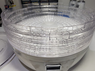
The one I decided upon was the $45 Anko Food Dehydrator from Kmart (Australia), although any dehydrator that has temperature controls within the required range would work. 

One other thing to check is that your spools will fit, although if there are trays in the way like there was for me, they can be easily removed. 

The dehydrator used in this post

The first thing to do once you purchase the dehydrator is test everything works, because after it is modified it will not be possible to return it. 

Now that it is confirmed working, the trays need to be removed. This will require only one tool, being the side-cutters, such as the ones that came with your printer. 

The typical side-cutters included with 3D Printers

Note that this can be a little messy, depending on how brittle the plastic is, so I recommend doing this in a place that can easily be cleaned or somewhere where mess doesn't matter. 

Finally, FOR SAFETY, wear safety glasses to prevent plastic from entering and damaging your eyes, possibly permanently.
It is for this reason that I hold NO liability for any damage or injury sustained from following this post under any circumstances.

To make the filament rolls fit in the dehydrator, it is quite a simple process. 

  1. Use the cutters to go around the inside edge of the tray and cut off the inside grid from the outside wall. In my case, I only needed to cut until I heard a crack and not all the way through. Also, not twisting while cutting significantly reduced the mess and flying plastic. 
  2. Push the middle of the tray until it separates from the walls. 
  3. Repeat for the remaining trays, although in my particular model the roll sat nice on the bottom tray, so I left that intact. 

The dehydrator with most of the racks cut out

Now that the modifications are complete, it is time to get drying!

Is It Worth It?

To test whether or not it is worth the money and effort, I tested with my Black 1kg PLA roll that was failing to print, and it was compared to a roll bought at the same time of the same type and supplier but of a different colour, being transparent green. 

To measure whether it had been improved or not, I checked:

  • How much popping there is, which would indicate moisture
  • The consistency of the flow from the nozzle
  • The smoothness of the walls of the print, as bubbles would cause the print to become rough
  • If the print actually finishes successfully

The prints were completed on an Ender 5 with a BL-Touch, with everything else stock. 

The models used were the "Cute Mini Octopus" and the 3DBenchie. Once I successfully got one material to print, I used the exact same settings and gcode to print the next one. 

Black and Green Octopi

Both turned out great once all the settings were dialled in, but the black dried filament had slightly less stringing, which is commonly attributed to moisture. Also, no popping was noticeable which means there was no evaporating moisture affecting the flow rate. Both prints were smooth and did not have any obvious under-extrusion or flow issues.

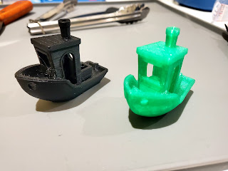
Black and Green Benchies
Interestingly, with the 3DBenchie, there was more noticeable stringing on the black than the green, but otherwise they both turned out great. They both completed and all features were present.

Conclusion

Other than the Benchies, there isn't really much evidence against this method, although it is far from scientific. Maybe in the future I will have to do a deeper dive into environment variables such as temperature and humidity, as well as other factors. If I had more time, I could make this a lot more reliable through multiple prints with each material of the same models and accurately controlling the environment, and not just with the air-conditioning.

The main flaw with my experiment was that I did not have a working print to compare to with the same roll from before drying, so I may revisit this in the future when the problem arises again.
But for now, I will continue to dry my filaments to ensure the flow rate is consistent and that there is no dilation of filament, but I would not consider it a must, at least for PLA. 

As always, if you liked this post, you can find all my other 3D Printing content here, and also through the tags below or in the sidebar. 

If you have any feedback or thoughts, please leave it in the comments below,  and thanks again for reading!

January 20, 2022

Bangle.js 2 - Hands-on, Impressions and Comparisons to Bangle.js 1

The Bangle.js series of watches instantly caught my attention back in 2019 for their customisability and freedom to install and create whatever I wanted, while still supporting common smart-watch features like notifications and health tracking. 

While I had a few small things I disliked about the first iteration, I was overall very pleased and excited for the future of the ecosystem. So when the second version launched in the second half of 2021, I was extremely excited to see what had been changed and improved.

Now that I have owned and worn both the Bangle.js 1 and 2 for a reasonable amount of time, I'm sharing my thoughts on what they do well, as well as what room there is for improvement.

Bangle.js 1 (Left) and Bangle.js 2 (Right)

Software

The awesome part of both of these watches is the underlying firmware, Espruino. This firmware works on many different microcontrollers, and allows for the device to be programmed using JavaScript, a language traditionally reserved for websites. This allows for a lower initial learning curve, as JavaScript is a relatively easy language to learn compared to the likes of C. 

Also, it allows for easy coding and testing via a web browser, as all the code can run natively, with a few obvious emulations of certain hardware sensors and components. 

With both watches using the same firmware, it means that most apps are cross-compatible, although some that rely on certain hardware features, such as the 3 buttons on the Bangle.js 1, may not work on both. An example of this is BangleRun, which only works with the Bangle.js 1.
This means that over 2 years after the original kickstarter launch, the ecosystem is filled with different watchfaces, apps and widgets to play around with. 

Another cool aspect of the Bangle.js ecosystem is the Widgets. These are little icons that can easily be added to any app to show things such as time, battery, bluetooth, steps and more. These widgets can even be companions to full apps, such as the notification widget that tells the user when there are notifications in the Messages app.

One other aspect of the Bangle.js software is that every component can be modified or outright replaced, including the firmware. This means that if there is an aspect of the overall system you don't like, such as the menus, settings or behaviour, all the code is open and freely available for you to modify. 

In addition to this, all aspects of the code accept community input through their respective Github repositories, so whatever improvements or changes you make can potentially help improve the experience for other users around the world. 

To see the list of available apps for these watches, visit the App Loader, and to start developing code yourself, checkout the numerous tutorials on the Espruino website.  

Hardware

The physical aspects of the Bangle.js 1 and 2 are really what set them apart. 

The most notable difference is the size and shape of the watches. While the Bangle.js 1 was round and quite large, the Bangle.js 2 is significantly smaller and also rocking a "squircle" face. I much prefer this new design, as it fits on my small wrist much better and isn't as heavy meaning I can actually forget the watch is there. 

Side Profile of Bangle.js 1 (Left) vs Bangle.js 2 (Right)

Another notable change, which I have already mentioned above, is the removal of the 3-button navigation in exchange for a touchscreen and a single side button design, comparable to the Amazfit Bip line of watches.

The Side Buttons on the Bangle.js 1 (Top) vs Bangle.js 2 (Bottom)

This change is a bit more controversial as a touchscreen is much less accurate and reliable than physical buttons, while on the other hand the touchscreen allows for more interaction styles not possible with buttons, such as interacting with a specific icon on the screen without "scrolling" through them to select the correct one. 

Sadly, one thing that did not change was the water-resistance rating. Both watches are rated for IP68, which means they can get wet and submerged, but swimming is not recommended. As a swimmer myself, this is not ideal, but knowing that it at least has a chance of surviving if I forget to take it off, I can live with it.

Another change with the screen is that the Bangle.js 1 had a beautiful, bright and clear OLED display, while the Bangle.js 2 has an always-on LCD that is a lower resolution. Personally I prefer this display as it allows for much longer battery life as well as an always on display, which are not both possible at the same time with an OLED. 

Speaking of battery life, while the Bangle.js 2 is advertised as having up to 30 days, in my experience it's closer to 1 week.
Although my experience may differ from the advertised time, this is due to how many apps I have installed as well as the amount of notifications I receive and how I have 24/7 heart rate enabled along with steps, all of which can significantly affect battery life. I have no doubt it is possible to reach the advertised time, it would just come with sacrifices.
More information on battery life and power draw can be found here.

Other changes to the hardware include an improved heart rate sensor, a better charger with less chance of a short-circuit, a barometer under the strap mount and standard 20mm interchangeable bands. 

To see all of the specifications, check out the product page here

Conclusion

Overall I think the Bangle.js 2 is a major upgrade over the Bangle.js 1 even with a few of the "downgrades", especially in regards to the screen, but with these being in exchange for a lighter, smaller design it's not really a downgrade, more just a design shift. 

For people with large wrists that want the brighter and higher resolution OLED as well as physical navigation buttons, the Bangle.js 1 is for them, while the Bangle.js 2 is for people who grieve their Pebble of yesteryear and don't want to sacrifice battery life and weight. 

For me personally, this will be staying on my wrist for the foreseeable future.


If you are interested in getting one for yourself, sadly only the Bangle.js 1 is available to buy at the time of writing, with the Bangle.js only sent out to Kickstarter backers. To buy the original and eventually the Bangle.js 2, checkout the Espruino Shop (not affiliated). 


As always, if you liked this review, you can find more here, and also through the tags below or in the sidebar. 

If you have any feedback or things that I should include or remove in future reviews and showcases, please leave it in the comments below, and thanks again for reading!

Ad